If you are thinking or you are in the process of making your own CNC machine, then most likely you will meet with the term GRBL. So in this tutorial we will learn what is GRBL, how to install and how to use it for controlling your Arduino based CNC machine.
Also, we will learn how to use the Universal G-code Sender, a popular open source GRBL controller software.
What is GRBL?
GRBL is an open source software or firmware which enables motion control for CNC machines. We can easily install the GRBL firmware to an Arduino and so we instantly get a low cost, high performance CNC controller. The GRBL uses G-code as input, and outputs motion control via the Arduino .
For better understanding, we can take a look at the following diagram:
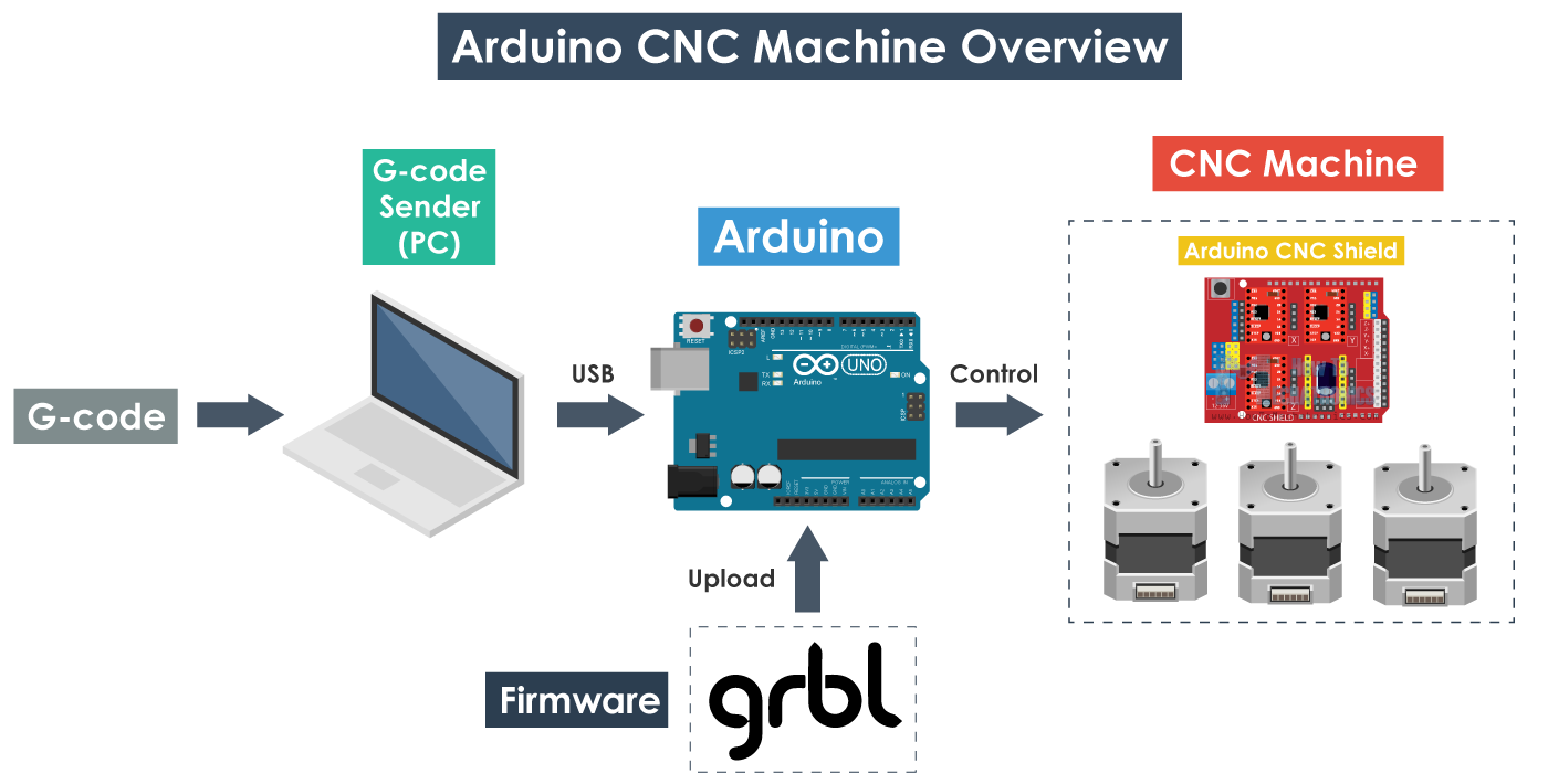
From the diagram we can see where the GRBL take place in the “big picture” of the working principle of a CNC machine. It’s a firmware that we need to install or upload to the Arduino so it can control the stepper motors of the CNC machine. In other words, the function of the GRBL firmware is to translate the G-code into motor movement.
Required Hardware
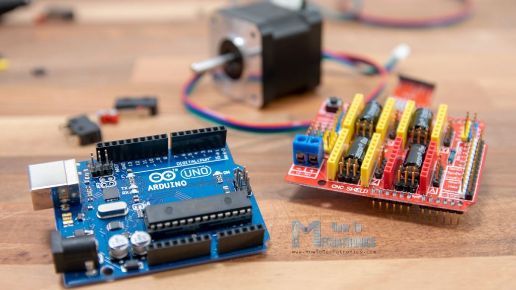
- Arduino – As we already said, we need an Arduino to install the GRBL. Specifically, we need an Atmega 328 based Arduino board, meaning that we can use either Arduino UNO or Nano.
- Stepper motors – Obviously, the stepper motors provide the motion of the machine.
- Drivers – For driving the stepper motors we need drivers and common choices when it comes to smaller DIY CNC machines (using NEMA 14 or 17 steppers) are the A4988 or DRV8825 drivers.
- Arduino CNC Shield – For connecting the stepper drivers to the Arduino, the easiest way is to use an Arduino CNC Shield. It utilizes all Arduino pins and provides an easy way to connect everything, the stepper motors, the spindle/ laser, the limit switches, cooling fan etc.
Please note that these are just he basic electronic components we need to understand how a CNC machine works.
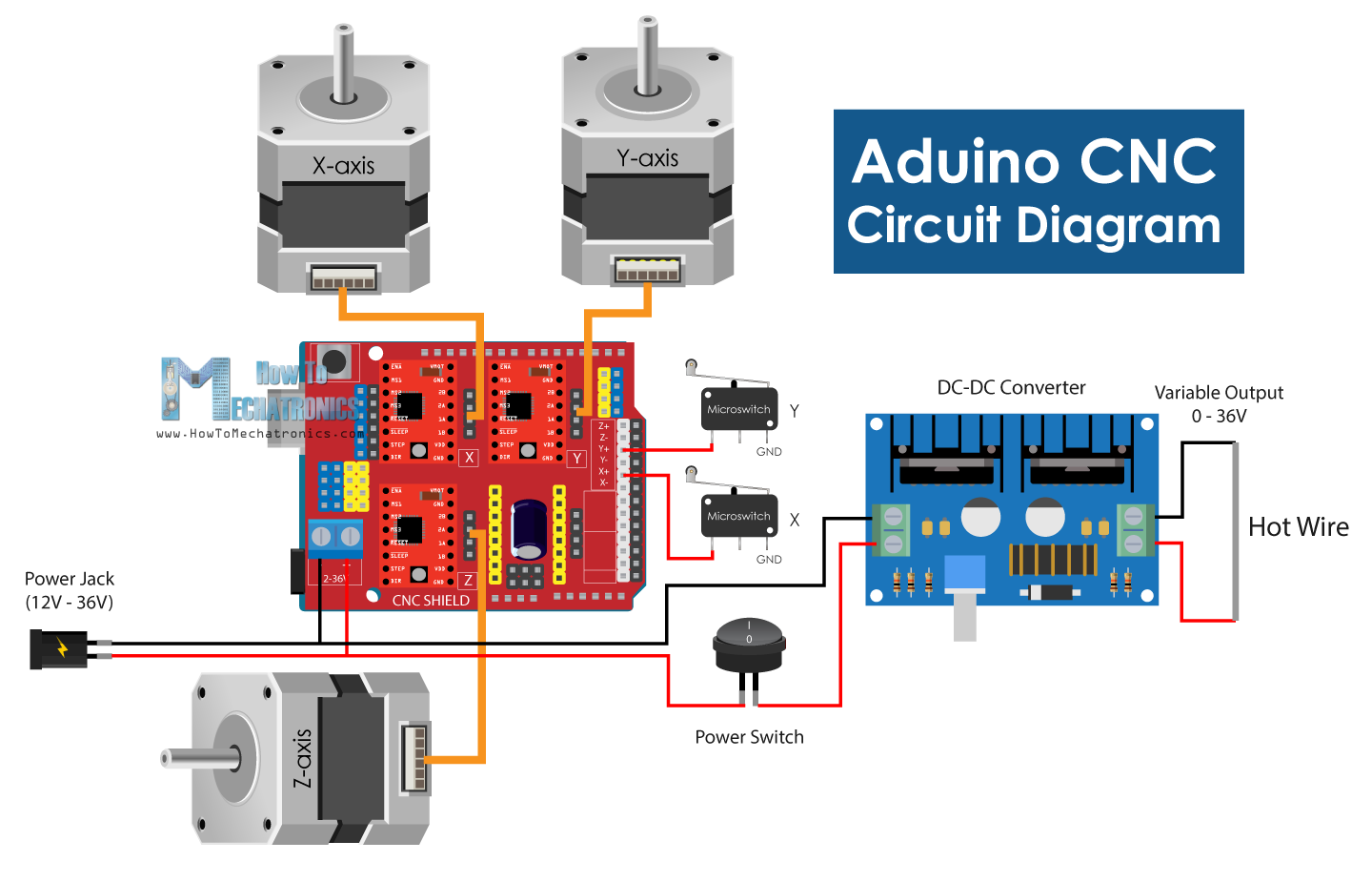
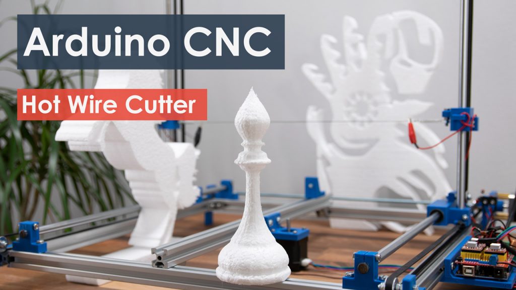
Actually, as an example of how everything needs to be connected we can take a look at my DIY CNC foam cutting machine.
You can check and get the main electronics components needed for building this CNC machine here:
- Stepper Motor – NEMA 17……………… Amazon / Banggood / AliExpress
- A4988 Stepper Driver…………………..… Amazon / Banggood / AliExpress
- Arduino CNC Shield ………………………. Amazon / Banggood / AliExpress
- Arduino Uno………………………………..… Amazon / Banggood / AliExpress
Disclosure: These are affiliate links. As an Amazon Associate I earn from qualifying purchases.
The main tool of this CNC machine is a hot wire which can easily melt or cut through a styrofoam and make any shape we want. For more details how I made the machine and how everything works you can check the particular tutorial.
Nevertheless, we will use this machine as an example throughout this article, because the same working principle applies for any other CNC machine, whether it’s mill or laser.
How to Install GRBL
First, in order to be able to install or upload the GRBL to the Arduino we need the Arduino IDE.
Then we can download the GRBL firmware from github.com.
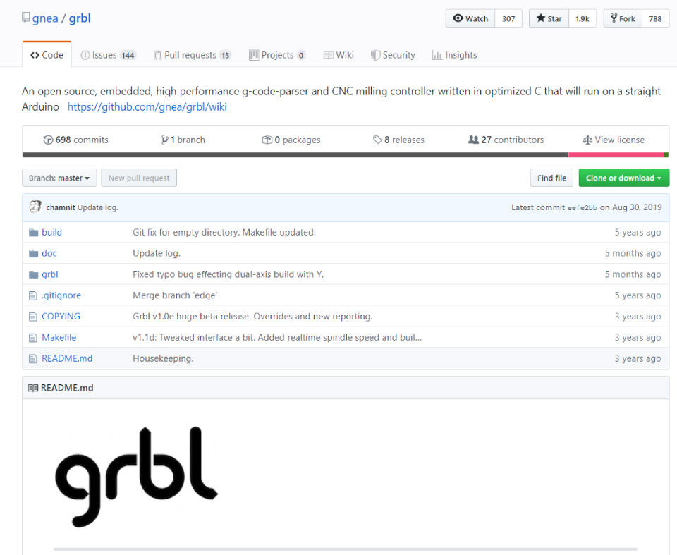
Download it as .ZIP file and then follow these steps:
- Open the grbl-master.zip file and extract the files
- Open the Arduino IDE, navigate to Sketch > Include Library > Add .ZIP Library…
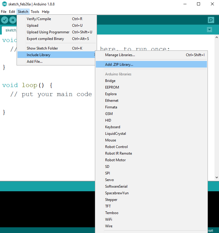
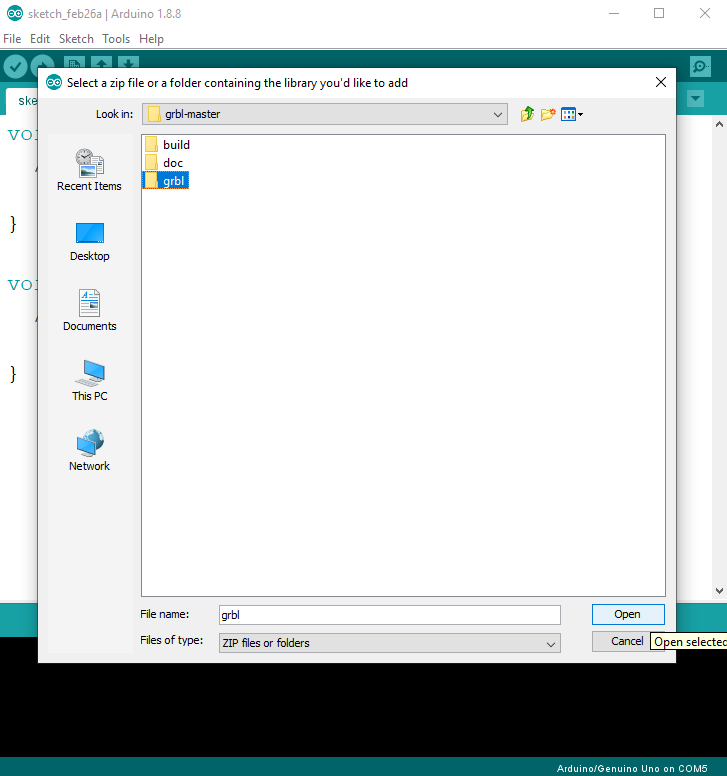
- Navigate to the extracted folder “grbl-master”, in there select the “grbl” folder and click the open file. Now we have to GRBL as an Arduino Library.
- Next, navigate to File > Examples > grbl > grblUpload. A new sketch will open and we need to upload it to the Arduino board. The code might look weird as it’s just one lines, but not worries, everything happens in the background in the library. So, we just have to select the Arduino board, the COM port and hit that upload button and we are done.
GRBL Configuration
At this point we should configure or adjust the GRBL to our machine. We can do that via the Serial Monitor of the Arduino IDE. Once we open the Serial Monitor we will get a message like “Grbl 1.1h [‘$’ for help]”. If you cannot see this message, make sure you change the baudrate to 115200.
If we type “$$” we will get a list of commands or current settings, and they appear something like this:
$100=250.000 (x, step/mm)
$101=250.000 (y, step/mm)
$102=3200.000 (z, step/mm)
$110=500.000 (x max rate, mm/min)
$111=500.000 (y max rate, mm/min)
$112=500.000 (z max rate, mm/min)
$120=10.000 (x accel, mm/sec^2)
$121=10.000 (y accel, mm/sec^2)
$122=10.000 (z accel, mm/sec^2)
All of these commands can be or should be adjusted according to our CNC machine. For example the with first command, $100=250.000 (x, step/mm), we can adjust the steps per mm of the machine, or we can specify how many steps the motor should make in order our X axis to move 1 mm.
However, I would suggest to leave these settings as they are. There is an easier way to adjust them according to our machine using the controller software, which we will explain in the next section.

GRBL Controller
So once we have installed the GRBL firmware, now our Arduino knows how to read G-code and how to control the CNC machine according to it. However, in order to send the G-code to the Arduino we need some kind of interface or a controller software which will tell the Arduino what to do. Actually, there are many both open source and commercial programs for that purpose. Of course, we will stick to open source, so as an example we will use the Univarsal G-code Sender.
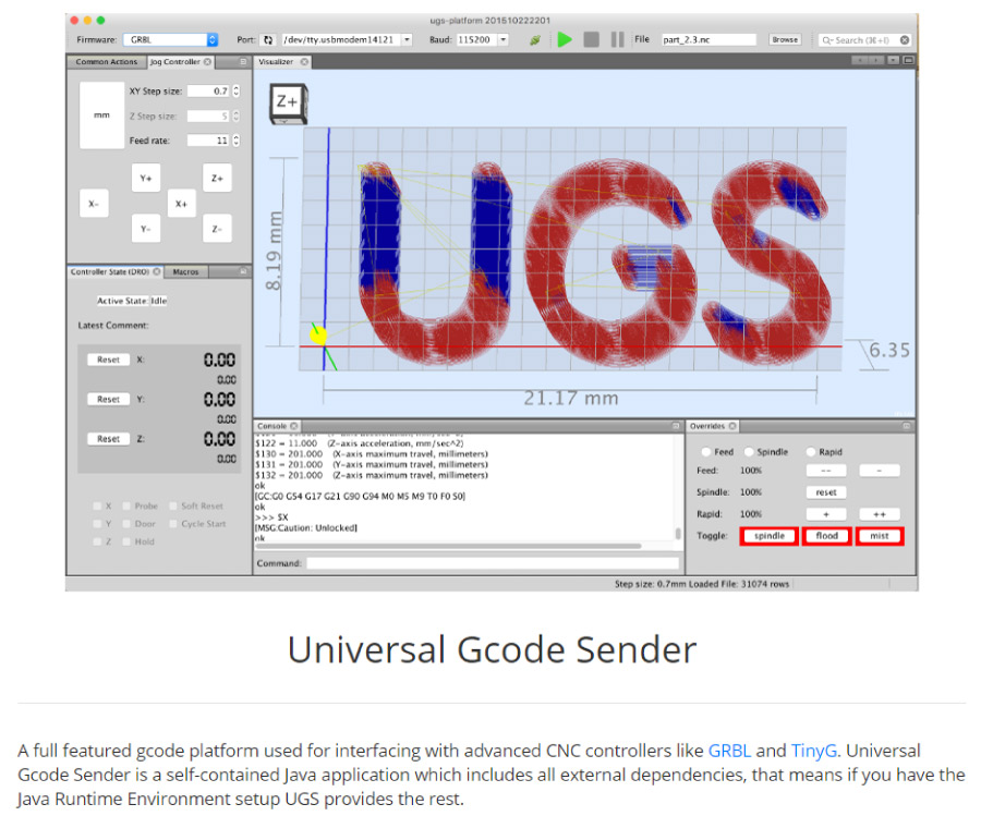
How to Use Universal G-code Sender
For this example, I will use the 2.0 Platform version. Once we download it, we need to extract the zip file, go the “bin” folder and open any of the executable “ugsplatfrom” files. This is actually a JAVA program, so in order to be able to run this program, first we need to install JAVA Runtime Environment.
Once we open the Universal G-code sender, first we need to configure the machine, or configure the GRBL parameters shown earlier. For that purpose we will use the UGS Setup Wizard which is much more convenient then manually typing commands through the Serial Monitor of the Arduino IDE.
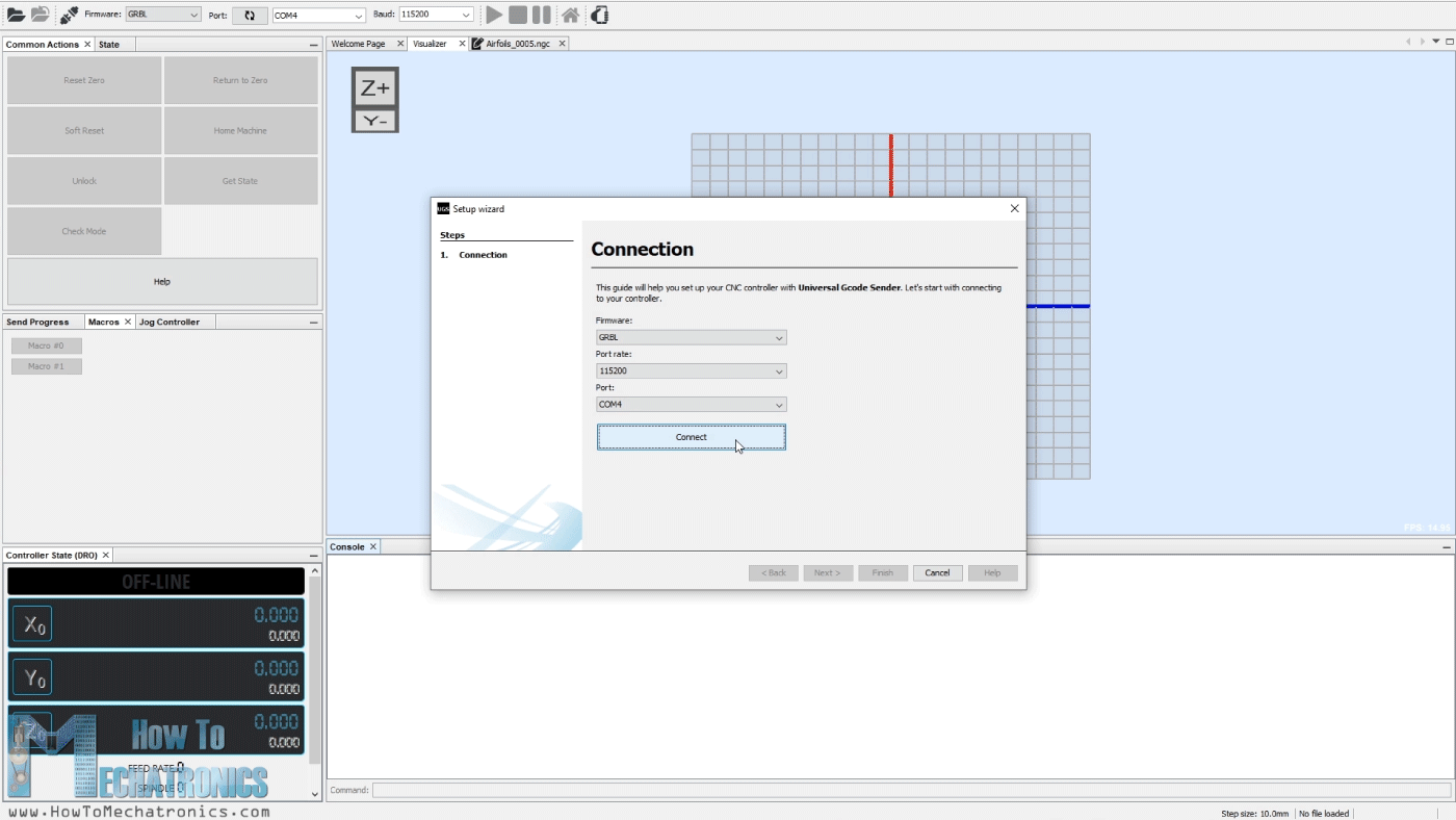
The first step here is to select the baudrate, which should be 115200, and the port to which our Arduino is connected. Once we connect the Universal G-code sender with the Arduino, in the next step we can check the direction of moving of the motors.
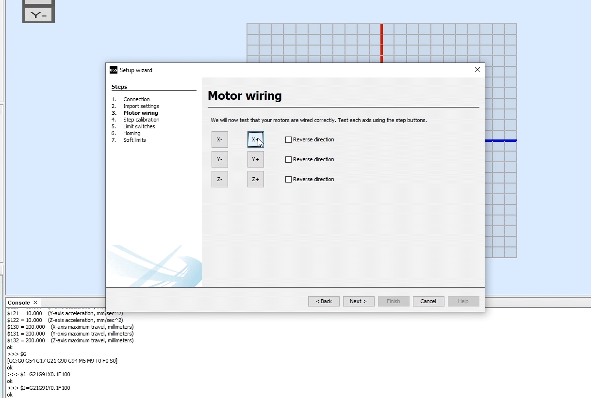
If needed, we can reverse the direction through the wizard, or by manually flipping the connection of the motor on the Arduino CNC Shield.
In the next step we can adjust the steps/mm parameter that we mentioned earlier. Here it’s much easier to understand how to adjust it because the setup wizard will calculate and tell us to what value we should update the parameter.
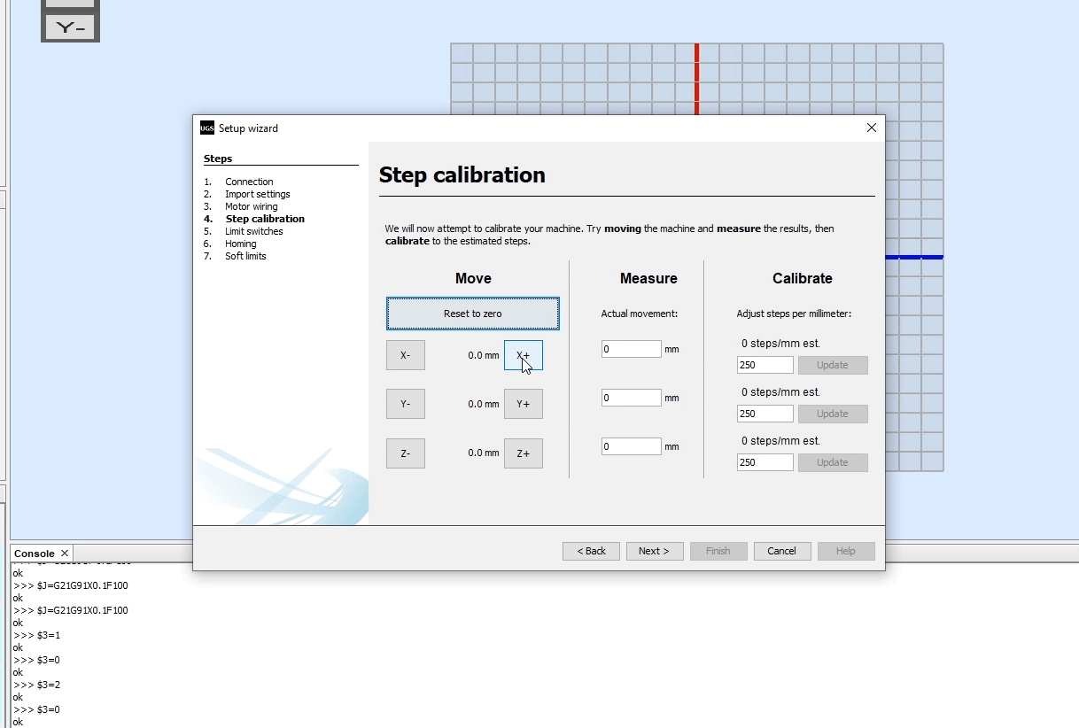
The default value is 250 steps/mm. This means, that if we click the move “x+” button, the motor will make 250 steps. Now depending on the number of physical steps the motor has, the selected stepping resolution and the transmission type, the machine will move some distance. Using a ruler we can measure the actual movement the machine made and enter that value in the “Actual movement” field. Based on this, the wizard will calculate and tell us to what value we should change the steps/mm parameter.
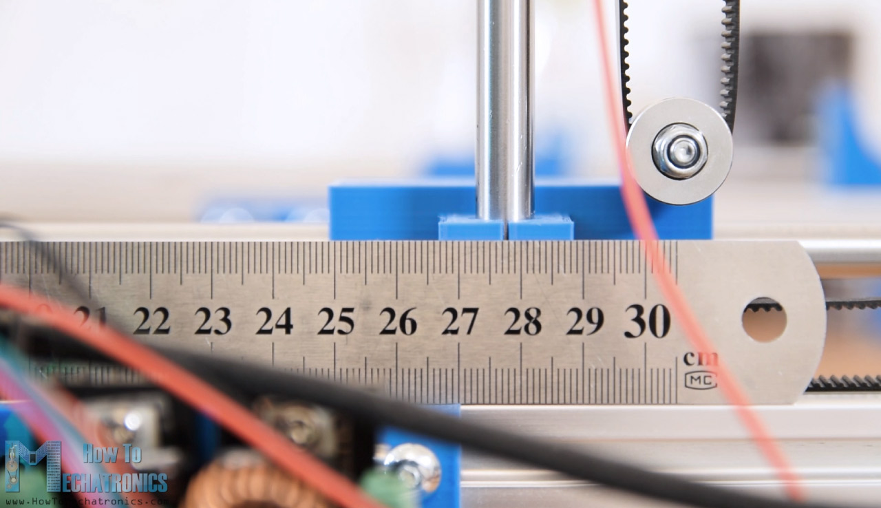
In my case, for the DIY CNC machine that I made, the machine moved 3mm. According to this, the wizard suggested to update the steps/mm parameter to a value of 83.
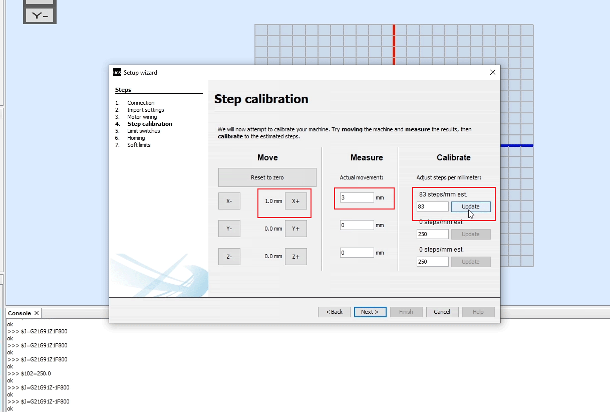
With this value updated the machine now moves correctly, 1 mm in the software mean 1 mm for the CNC machine.
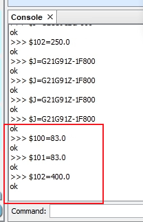
In the UGS console, as we make each action we can see the commands that are executed. We can notice that by updating the steps/mm parameter the UGS program actually sent to the Arduino, or the GRBL firmware the command we mentioned earlier. This was the default value: $100=250.000 (x, step/mm), and now we updated to value of 83 steps per mm: $100=83.
In the next step we can enable the limit switches and test whether they work properly.
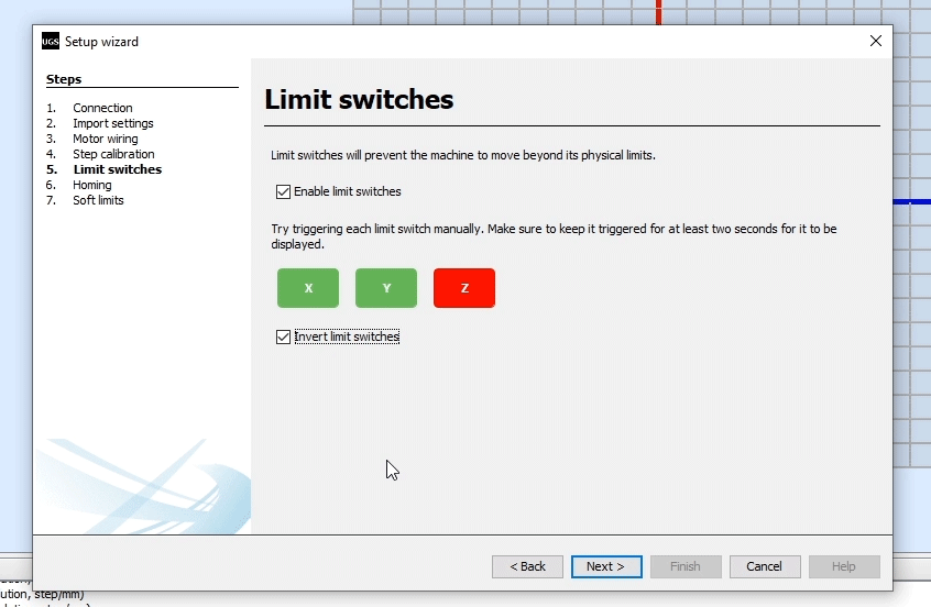
Depending whether they are Normally Open or Normally Closed connection, we can also invert them here.
Here it’s worth noting that sometimes we need to disable Z axis limit switch. That was the case with my DIY CNC Foam Cutting machine where I didn’t need the Z axis limit switch and I had to disable it in order to be able to properly home the machine. So, to do that, we need to edit the config.h file which is located in the Arduino library folder (or Documents\Arduino\libraries).
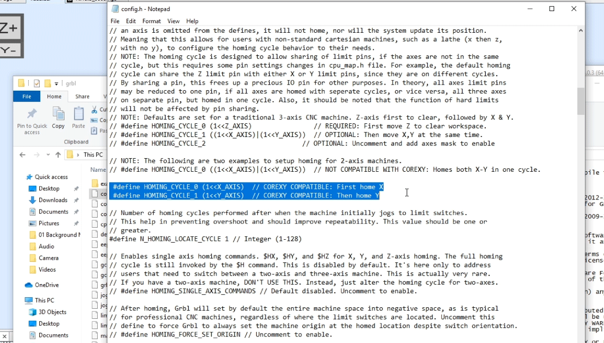
Here we need to find the homing cycle lines and comment the default set for 3 axis CNC machine and uncomment the setup for 2 axis machines. In order the changes to take effect we need to save the file and reupload the grblUpload sketch to our Arduino board.
Nevertheless, in the next step we can either enable or disable the homing of the CNC macing.
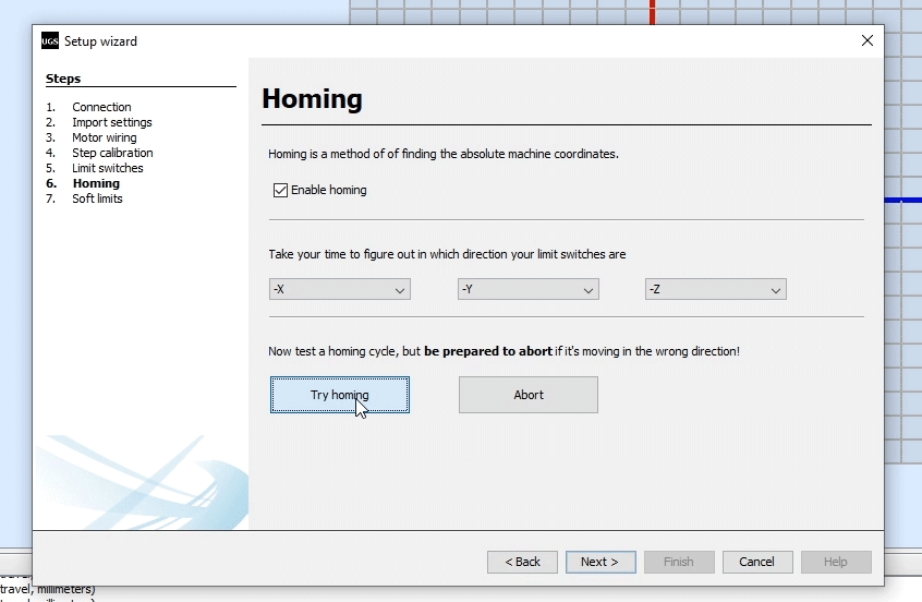
Using the “Try homing” button the machine will start moving towards the limit end switches. In case it goes the opposite way we can easily invert the direction.
Finally, in the last step of the Setup wizard we can enable soft limits for our CNC machine.
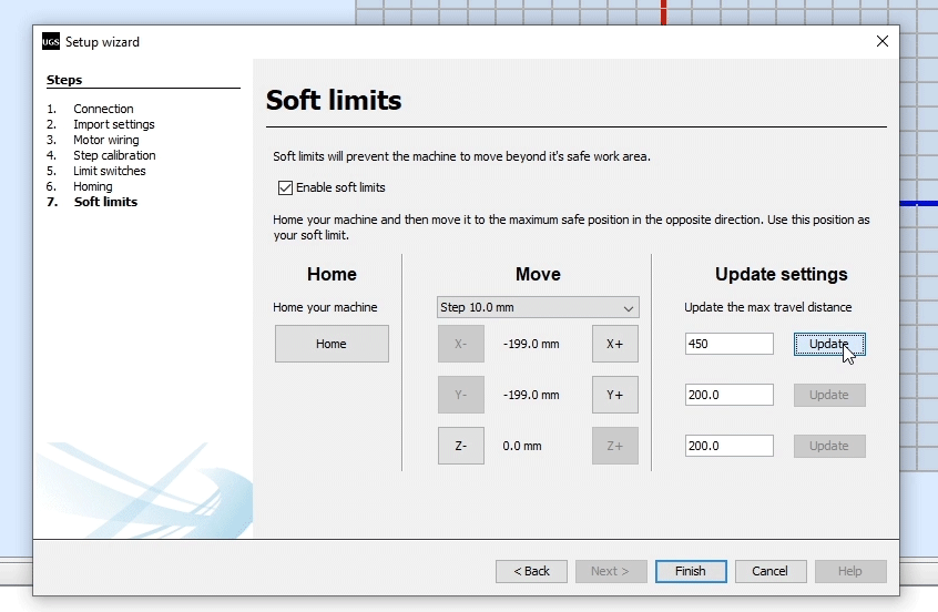
The soft limits prevent the machine from moving beyond the set working area.
Conclusion
So, thanks to the GRBL firmware and the Arduino, we can easily setup and get our DIY CNC machine running. Of course, we covered just the basics in this tutorial, but I think that was enough to understand how things work and how to get our first CNC machine up and running.
Of course, there are many other settings and features available, as the GRBL is really capable CNC controller firmware. The GRBL documentation explains all of that in details, so you can always check them on their wiki page on github.com.
Also, there are many other open source GRBL controller programs like the Universal G-code Sender, and here are few: GRBLweb (Web Browser), GrblPanel (Windows GUI), grblControl (Windows/Linux GUI), Easel (Browser based) etc. You should explore them and see which one suits you the best.
You are a really good Engineer! I mean this in the high level Professional sense. Thanks for all this really useful information
Cheers
Gary
Hello, thanks for sharing this information, I ask you a question, I have a “core XY” cnc laser that works fine, but I had to deactivate the limit switches because they caused random errors during printing, even though they were not pressed.
did you make any modifications to the firmware? Thank you
Hey, thanks! Well the problem might be electrical noise which triggers the switches. You can try to connect 1k to 4.7k pull up resistor to 5V and a decoupling capacitor to GND for filtering the noise.
Salute from Dublin Dejan. I was hoping to ask a quick question if u have time?
Q. How easy is it to connect up TB6600 stepper drivers with Nema 23’s to the CNC Shield/Arduino? I’m reading for information all the time but this tech is new to me. The info in this article is helping me no end bro. Thanks for this bcos I was loost on how to set up the Arduino with GRBL.
I got a Laser engraver about 218 months ago and only recently took it out of its box and got it working with Laser GRBL and it works fine. It is using 2 small steppers. The Y & X axis have them bcos u set the height to Laser.
The CNC ROUTER is far more complicated for me to get my head around but ur article has been a real eye opener for me and is making things easier to grasp now.
Do u have any articles on TB6600 steppers with 23’s and Arduino, etc for the CNC router build? I would be grateful for any tips u can give. Thanks for ur time my friend.
Hey, connecting up TB6600 drivers with NEMA 23 should is not so complicated. Though, I’m sorry at this moment I don’t have article it. They are on my do-to list, but it will take me some time to make them. I hope you already got it working.
Cheers!
At a quick glance this article seems comprehensive. I appreciate the time and effort you put into making my life easier. While I have no immediate interest in engraving, laser-printing, or building a CNC machine for manufacturing small parts, I have been working on a plotter for printing PCB boards I can later etch in a ferric chloride solution. I have designed and 3D printed my CNC plotter PLA parts, ordered the necessary parts from various sources, such as stainless steel rods, NEMA 17 stepper motors, square flange linear bearings, etc. My assembly is nearly completed, and I needed a “brain” for the machine, which I am hoping this article has provided me with. So, thank you very much for this insightful article.
Thanks a lot. Very very useful.
NPS
Hi this is a very helpfull explanation for a movie like me.I have build my mini CNC engraver but struggle to make the machine move.This is however only due to my lack of knowledge of arduino and grbl coding.I will however get there.Thank you for explonation on how everthing fits together.
Hi Dejan,
thanks for this tutorial! I realy appreciate this but have some questions…
Which kind of CNC shield do you use? In the picture it looks like you’re using the v3.0 which is not compatible to grbl 1.1 afaik. I use the same shield and use actually grbl 0.8 to get the motors run. Do you have any problems/errors with grbl 1.1 and shield v3.0?
Thank you!
Hey, thanks! Well the CNC shield I’ve been using was v3.0, or that’s what it says on the board. I didn’t encounter any problems/errors, so I could say anything about it.
This issue is really fast. Can you talk about the connection and difference between 3D printing and CNC?